
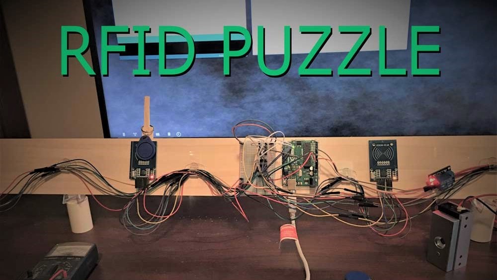
Build Your Own Radio Frequency Identification (RFID) Puzzle
Building your own RFID puzzles is a fun experience. You can learn a lot about the technology and how it works and its limitations. In addition, you can save some money in the process.
Escape The Roomz (ETR) Team members Ace and Amy have built two rooms for United Way fundraisers. For the one they put together last August, we upped the tech from the previous room they designed. Two of the puzzles included: 1) A toybox with an RFID lock and 2) A fireplace stocking RFID puzzle where the players must place four Christmas stockings in the correct order to release a needed item to solve another puzzle. This article will describe the process I used to build the fireplace puzzle.
Research
Once you have an idea of what puzzle you want to build, the next step is to research the internet to see what information is available. Alternately a book or eBook is often a good source of information. I did not locate a good book for this project, so I went the route of scouring the internet for information. For these types of projects, it’s also good if you can see the assembled project in action, so the search took me to YouTube.
The YouTube search paid off when I searched for an RFID escape room puzzle. I found a channel called Playful Technology out of the UK that has videos on tinkering with technology for making puzzles. A gentleman by the name of Alastair Aitchison has created several useful videos. Alastair is a programmer, game designer, and teacher as seen in these videos.
A video I found particularly useful is called Escape Room Object Placement Puzzle using Arduino/RFID. Alastair did an excellent job walking through the design and construction of an object placement puzzle. He also provides a link for downloading the Arduino code, wiring diagram, and additional documentation that allowed me to build the puzzle. I was required to become a Patreon member to access this information, but for me it was well worth it!
RFID Puzzle Components
Here is a list of the hardware used to build this puzzle:
| Item | Qty |
| RFID Sensors with ID cards and key fobs | 4 |
| Arduino Uno Microcontroller | 1 |
| 5V Relay | 1 |
| 12V Magnetic Lock | 1 |
| 12V Power Supply | 1 |
| Breadboard | 1 |
| Jumper Wiring (package 120 wires) | 1 |
Here is a block diagram of how the components of this puzzle communicate:
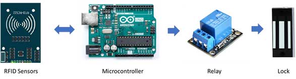
RFID Sensors
The RFID sensors are circuit cards designed to look for a specific signature from an ID card or key fob. The intended design and use of these cards is for key card / smartcard security access. In other words, the cards and sensor are an alternative to using key locks for access through doors, gates, etc. When a key card with the correct signature is placed near the RFID sensor, the sensor communicates this to the microcontroller.
Microcontroller
The Arduino microcontroller is a popular item with a wide variety of uses for controlling sensors and actuators. You can program the Arduino to initialize the RFID sensors, identify the ID codes from the ID cards and the order they must appear in, and to control the relay using code that you can obtain via Alastair’s documentation. The software is quite useful for understanding and debugging the operation of this puzzle. The Arduino also initializes or resets the signal to the 5V relay when powered and the reset button is depressed.
5V Relay
The relay basically operates as a switch. When initialized, it powers a magnetic lock which will hold an item in place until it receives a signal from the microcontroller. When the signal is received it de-energizes the magnetic lock.
Lock
The magnetic lock holds an item in place until it is de-energized. A 12V DC supply provides power to the magnet. Note that these locks come in different strengths – the one we used was 60KG (132 lbs) and had more than sufficient holding power. A 600-lb lock is also available.
The parts, including mounting tape and board, cost around $90 USD.
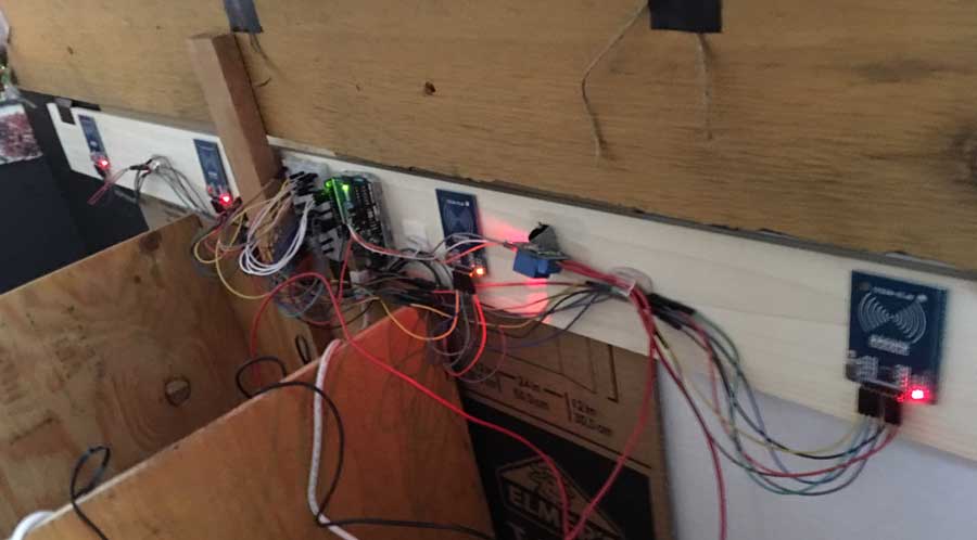
Assembly
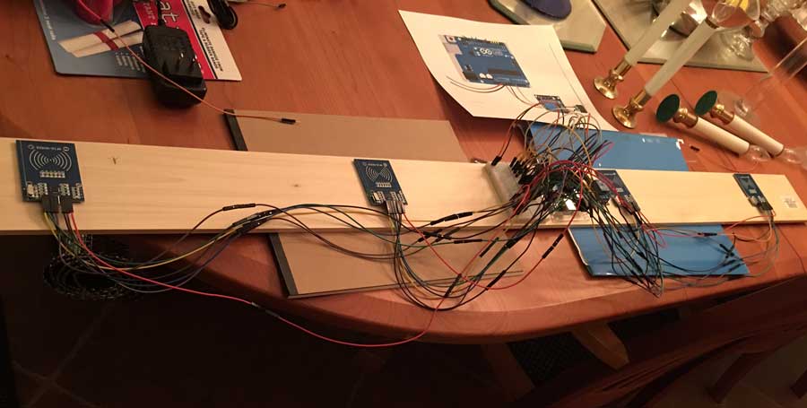
Ace and Amy provided the distances between hooks on the fireplace that corresponds to the distances between the RFID sensors. Double-sided mounting squares were used to attach these sensors and other components to the board. This allowed for a non-permanent installation so that the sensor location or other component placement could be readjusted as needed. The wiring diagram provided by Alastair was clear and easy to follow. Multiple wires had to be connected together to reach from the breadboard to the RFID sensors.
Uploading Code and Testing the Puzzle
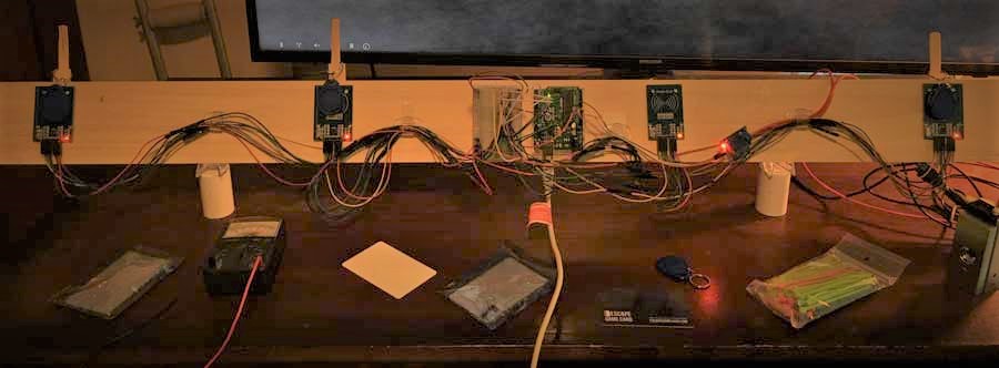
Next, I set the puzzle upright on a desk near a PC so that I could upload the software to the Arduino and test the puzzle. I temporarily attached popsicle sticks so that I wouldn’t have to hold the key fobs in place. Then I connected the PC to the Arduino and uploaded the code. Using the ID codes that came with the RFID sensors, I updated the puzzle codes. Using the serial monitor function, I was able to monitor whether the puzzle was operating correctly.
Here is a snippet of the code and output of the serial monitoring:
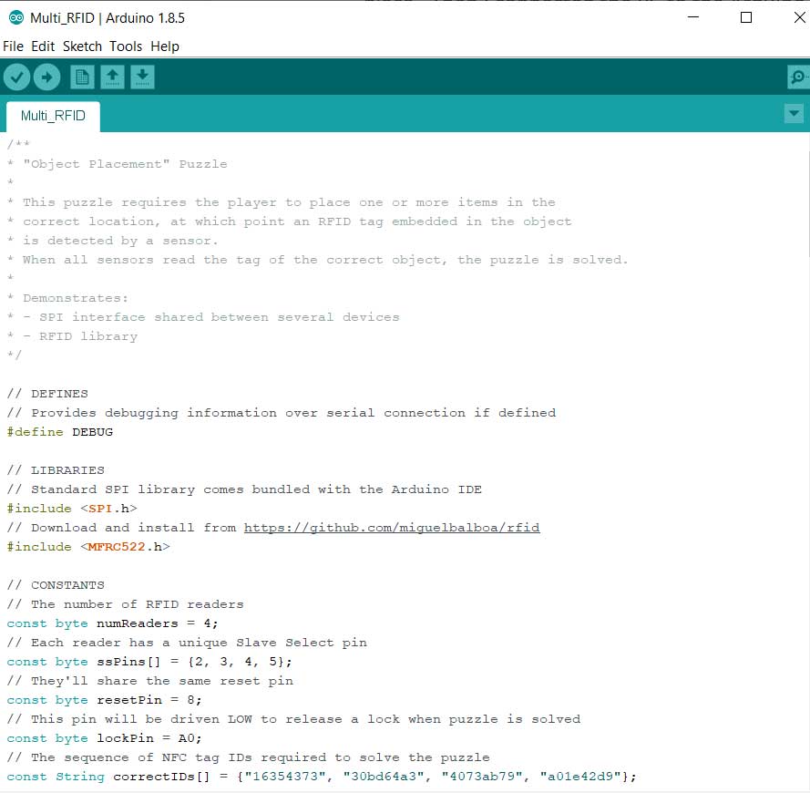
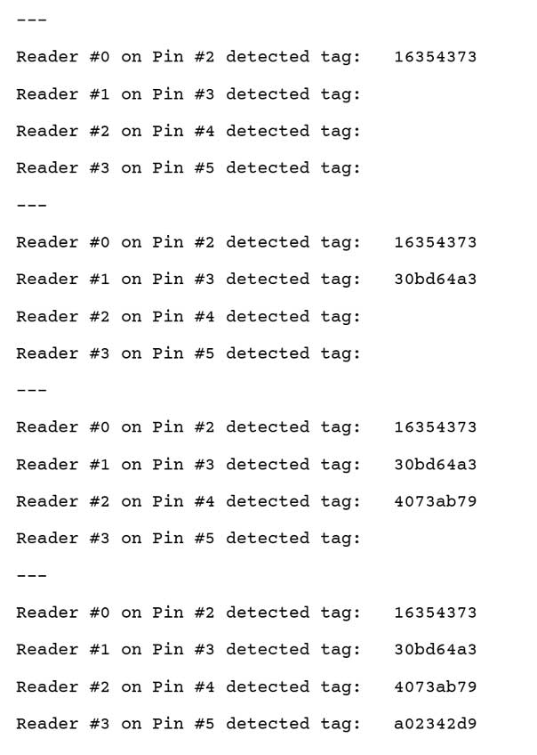
One difficulty I was having was getting the key fobs to consistently register. I maximized the gain setting and tested different communication speeds between the RFID sensors and the Arduino to optimize communication.
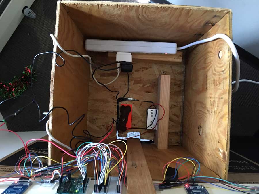
After completing the setup, I transported the puzzle to the site for installation into the fireplace. We were fortunate because we had not communicated the construction of the fireplace and yet it fit like a glove!

Then Ace and Amy attached the magnetic lock to the trap door at the bottom of the boxlike structure and we tested the unit. We further tested operation during the room beta-testing.
What We Learned
One of the advantages to putting a puzzle together yourself is that you will better understand how it works and the limitations. Two things we learned included: 1) Limitation in the distance between an ID card (or key fob) and the RFID sensor needed to activate the puzzle, and 2) Implementing a back-up strategy to ensure the trap door opens.
ID card (or key fob) distance from RFID Sensor:
One concern I had during the testing of the puzzle is that the key fob or ID card needed to be very close to the RFID sensor (within 1.5 inches). This could have been due to one of the following reasons:
- The wiring connecting the RFID sensors to the Arduino were not shielded. This may have allowed RF interference to affect the puzzle. I believe this was a contributing factor because it was more noticeable in my office where I have a lot of wireless devices versus the escape room which had no wireless devices (other than our phones).
- The design of the RFID sensors I used had limited distance by design. The ID cards and key fobs were passive (not battery-powered). The ID cards worked better than the key fobs, so we placed those into the Christmas stockings. What further complicated this is that there was some additional separation between the Christmas stockings and the fireplace. Also, the stockings were sometimes placed at a slight angle to the fireplace.
Wi-Fi Power Backup:
While the puzzle worked much better in the conference room than during testing in my office, it didn’t work correctly 100% of the time. We first came up with a back-up plan using a Wion wireless power strip. In theory, this would have allowed us to manually de-energize the puzzle and release the trap door. Using this approach required eyes on the players (using cameras). Also, we needed to have the stockings marked to know when to turn off the power strip if the puzzle didn’t work.
We had one small problem with this approach (okay, one big problem). We learned that this conference room had no wi-fi access. Fortunately, Ace was able to find a remote switch with its own transmitter/receiver. The backup solution worked great! The players couldn’t tell that Ace and Amy were controlling the puzzle and were quite impressed!
If you’re interested in building this puzzle, we have included links below with our affiliate links to purchase them. One thing I found as I was reviewing Alastair’s YouTube channel is that he added a video comparing the RFID sensor used here to other models. He found that the PN5180 has a much larger range, so I will try to find and include a link to that part as well. The downside is that the documentation and software library used for this puzzle will be different than that needed to use the PN5180.
If you build this puzzle, please comment below and let us know how it went and which sensor you are using!
Hi, thanks for the feedback! Yes you could do that. I think this relay is rated up to 10 amps, but that might be pushing it. Check out the description on Amazon or specs for whatever relay you are wanting to use for more details.
Hello,
This is a very nice project.
Can it be modified in order to turn on a servo/motor?
Thx